
Combining a Raspberry Pi and camera module is nothing new to most, but the linux internals are less well known. So let’s get uncomfortable and try to dive a bit deeper into the soft- and hardware stack that serves as a basis of many hacker projects worldwide.
From light to digital: the camera sensors
I already dived into the tech that makes camera sensors be able to capture analog light waves into digital data. If you didn’t read that article or simply want to refresh your memory please read this article first: astrophotography from a beginners perspective (part 2) – cameras and sensors
MIPI-CSI2
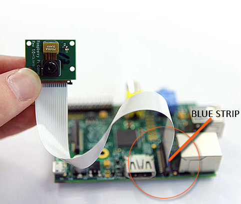
When you get a camera board there is only one way to hook it up to your Raspberry Pi: through the MIPI-CSI 2 port. MIPI is an alliance that created the DSI (Display Serial Interface) and CSI (Camera Serial Interface) standards. CSI2 is an evolution of the CSI standard that brought RAW-16 and RAW-20 color depth and basically is one of the most important protocols to hook up your camera to your embedded computer board. RPIs and their camera boards come with a 15-pin or 22-pin connector. The 15-pin connector is mostly seen on standard Raspberry Pi models (A&B series) and Pi camera modules, while the 22-pin is on Raspberry Pi Zero-W and Compute Module IO Board. The connect in-between is called a Flat Flexible Cable (FFC).
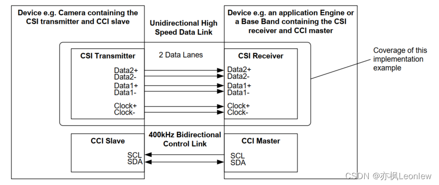
So MIPI-CSI2 is a high speed data interface specially designed for cameras. It uses MIPI D-PHY, MIPI C-PHY, MIPI A-PHY on the physical layer. The basis is differential signaling on both the clock and data pairs, which are often referred to as ‘lanes’. Depending on the required bandwidth more data lanes can be added. The protocol is therefor serialized over one or multiple data pairs. The clock defines the speed at which the data is transferred and can be different depending on the camera attached. The CSI protocol is one-directional and therefor from a device topology stand of view we always speak of a CSI transmitter and CSI receiver. The transmitter is the camera transmitting pixel data, the receiver is the chip (SOC/FPGA/ASIC/…) taking the pixel data in for further processing. On top of the data lanes there is also a low speed I2C channel used for probing the camera and configuration. This channel is often referred to as the CCI (Camera Control Interface) channel. The picture below shows a CSI interface with 2 data lanes, one lane for the clock, and the I2C channel:
One thing you have to particularly understand here is that the data that goes through the CSI interface is pure sensor data. It doesn’t not like 24-bit or similar bitmap data that you’re familiar with. As said the receiver is most likely some SOC or FPGA that knows how to deal with the RAW data that it receives. It’s a feature of your SOC that you have to look for if it supports MIPI-CSI, which in case of a Raspberry Pi is fortunately the case. From there on the complexity only increases. Depending on your receiver the data may now travel directly into the video4 linux subsystem that is part of the linux kernel, or maybe makes a little detour through an ISP. The latter is a hardware accelerator for offloading the CPU in tasks that are focussed on improving image quality through all sorts for algorithms. The ISP (Image Signal Processor) can be internal on your SOC, but can also be an external chip that passes through data using MIPI-CSI while meanwhile performing a set of pre-defined image quality booster algorithms. That’s kind of the high level overview that you should keep in mind while we go through some of the detail.
Sensor probing
MIPI-CSI is not a plug-and-play protocol in such way that you attach a sensor to your board and that you’re all settled. We can’t just go auto-detect the sensor without doing some driver specific magic and device tree configuration. As we already learned that’s where the I2C channels is used for. I2C off course is standardised, but the control registers of the sensors are not. Those is mostly hidden in a well protected datasheets or application notes that are not readily available. Sensor companies try to heavily guard their IP with NDA’s and so forth. So it’s not so straightforward to implement a new sensor into the kernel without the help of the manufacturer, unless you’re experienced in camera sensor drivers and are willing to spend some time hacking on its features.
Let’s start with defining the sensor. This typically happens in the device tree. Either directly as it is with most embedded systems (fixed purpose machines) or via device tree overlays as typically found in Raspberry Pi boards. With RPI is mostly a matter of adding the sensor device tree overlay into your boot config file. With other embedded systems is mostly adding the sensor specific config to your device tree that you compile together when you build the final image. Either way, the device tree description for both are the same, it’s just a matter of how the bootloader loads the data that is different. If you’re looking for documentation about the device tree configuration of the sensors that are supported by the linux kernel I can recommend open this link: https://www.kernel.org/doc/Documentation/devicetree/bindings/media/i2c/
So even though MIPI-CSI is the data interface, the sensors binding are found in the kernel under I2C as that is the protocol used for probing and controlling the sensors. Now let’s have a look at one of the popular sensors from nowadays, the imx290:
The Sony IMX290 is a 1/2.8-Inch CMOS Solid-state image sensor with
Square Pixel for Color Cameras. It is programmable through I2C and 4-wire
interfaces. The sensor output is available via CMOS logic parallel SDR output,
Low voltage LVDS DDR output and CSI-2 serial data output. The CSI-2 bus is the
default. No bindings have been defined for the other busses.
You have to define a bunch of required node properties, but there are also optional properties. Here is an example:
&i2c1 {
		...
		imx290: camera-sensor@1a {
			compatible = "sony,imx290";
			reg = <0x1a>;

			reset-gpios = <&msmgpio 35 GPIO_ACTIVE_LOW>;
			pinctrl-names = "default";
			pinctrl-0 = <&camera_rear_default>;

			clocks = <&gcc GCC_CAMSS_MCLK0_CLK>;
			clock-names = "xclk";
			clock-frequency = <37125000>;

			vdddo-supply = <&camera_vdddo_1v8>;
			vdda-supply = <&camera_vdda_2v8>;
			vddd-supply = <&camera_vddd_1v5>;

			port {
				imx290_ep: endpoint {
					data-lanes = <1 2 3 4>;
					link-frequencies = /bits/ 64 <445500000>;
					remote-endpoint = <&csiphy0_ep>;
				};
			};
		};
So what we can understand here is that you must add the sensor description to an existing I2C node which here is referred to as &i2c1.The sensor node itself will have a specif I2C address which in this case is 0x1a and is defined in the reg property. The compatible property is also important as this defines what driver will be loaded by the kernel once the sensor has been probed. Next make sure to set the correct value for the clock-frequency. Also set the correct supply voltages, and as seen in this examples there is also an optional reset pin that can be defined. Finally there is the port subnode with required endpoint subnode. This is the link to the MIPI-CSI! You can easily understand the amount of MIPI data-lanes in use here, and the remote-endpoint is the reference to the MIPI-CSI phy which is just another node in the device tree that describes the MIPI-CSI.
So by looking into this configuration we already learned a few important things. We know the I2C interface in use, we know which sensor will be loaded, at which I2C address it can be found and we know which MIPI phy it is connected too. We also know which drivers will be used. Now if we start looking into the linux kernel for which driver covers the sony,imx290 compatibility we end up here: imx290.c.
The driver for example mentions what device tree config it is compatible with:
static const struct of_device_id imx290_of_match[] = {
	{
		/* Deprecated - synonym for "sony,imx290lqr" */
		.compatible = "sony,imx290",
		.data = &imx290_models[IMX290_MODEL_IMX290LQR],
	}, {
		.compatible = "sony,imx290lqr",
		.data = &imx290_models[IMX290_MODEL_IMX290LQR],
	}, {
		.compatible = "sony,imx290llr",
		.data = &imx290_models[IMX290_MODEL_IMX290LLR],
	}, {
		.compatible = "sony,imx327lqr",
		.data = &imx290_models[IMX290_MODEL_IMX327LQR],
	},
	{ /* sentinel */ },
};
As you can see the driver supports a few sensors all quite similar to each other, some have color pixels, other or just mono sensors.
The probing and removing functionality is often a means of allocating the according memory in the kernel. It also creates a new Video4Linux (V4L) subdevice, but more on that in a moment. It contains the I2C communication that goes over the Camera Control Interface (= the I2C control channel), look for function calls such as cci_write. Aside of that we also have power management functionality in the driver, the V4L streaming control, clocking/timing, passing through the V4L configuration commands (gain, format, etc.) to the sensor, and here and there some notes on how the sensor works.
/*
 * The IMX290 pixel array is organized as follows:
 *
 *     +------------------------------------+
 *     |           Optical Black            |     }  Vertical effective optical black (10)
 * +---+------------------------------------+---+
 * |   |                                    |   | }  Effective top margin (8)
 * |   |   +----------------------------+   |   | \
 * |   |   |                            |   |   |  |
 * |   |   |                            |   |   |  |
 * |   |   |                            |   |   |  |
 * |   |   |    Recording Pixel Area    |   |   |  | Recommended height (1080)
 * |   |   |                            |   |   |  |
 * |   |   |                            |   |   |  |
 * |   |   |                            |   |   |  |
 * |   |   +----------------------------+   |   | /
 * |   |                                    |   | }  Effective bottom margin (9)
 * +---+------------------------------------+---+
 *  <-> <-> <--------------------------> <-> <->
 *                                            \----  Ignored right margin (4)
 *                                        \--------  Effective right margin (9)
 *                       \-------------------------  Recommended width (1920)
 *       \-----------------------------------------  Effective left margin (8)
 *   \---------------------------------------------  Ignored left margin (4)
 *
 * The optical black lines are output over CSI-2 with a separate data type.
 *
 * The pixel array is meant to have 1920x1080 usable pixels after image
 * processing in an ISP. It has 8 (9) extra active pixels usable for color
 * processing in the ISP on the top and left (bottom and right) sides of the
 * image. In addition, 4 additional pixels are present on the left and right
 * sides of the image, documented as "ignored area".
 *
 * As far as is understood, all pixels of the pixel array (ignored area, color
 * processing margins and recording area) can be output by the sensor.
 */
Video4Linux
During the previous probing stage we already talked about the Video4Linux things that a camera driver needs to implement. You mat wonder what Video4Linux actually is. V4L is a kernel framework used to interface with video capture devices in Linux environments. It provides an API for handling various multimedia devices such as webcams, TV tuners, and digital cameras. Camera modules that are compatible with V4L can be easily integrated into Linux-based systems, allowing applications to capture and manipulate video streams from these devices. To make new kernel drivers for devices that need to be controlled through the Video4Linux framework there are a couple of APIs that you need to implement:
- Device Discovery and Enumeration:
VIDIOC_QUERYCAP: This ioctl is used to query the capabilities of the device and determine if it supports V4L2.VIDIOC_ENUM_FMT: Enumerates the supported video formats and frame sizes for the device.
- Device Control:
VIDIOC_S_FMTandVIDIOC_G_FMT: Set and get the format of the video stream (resolution, pixel format, etc.).VIDIOC_S_PARMandVIDIOC_G_PARM: Set and get parameters like frame rate, exposure, and other camera-specific settings.
- Buffer Management:
VIDIOC_REQBUFS: Requests buffers to be allocated for video capture.VIDIOC_QUERYBUF: Queries information about the allocated buffers.VIDIOC_QBUF: Enqueues an empty buffer for capturing video data.VIDIOC_DQBUF: Dequeues a filled buffer containing captured video data.
- Streaming Control:
VIDIOC_STREAMONandVIDIOC_STREAMOFF: Start and stop video streaming.
- Control Operations:
VIDIOC_QUERYCTRL: Query the supported controls (e.g., brightness, contrast, zoom).VIDIOC_G_CTRLandVIDIOC_S_CTRL: Get and set control values.
- Event Handling:
VIDIOC_DQEVENT: Dequeues events from the event queue.VIDIOC_SUBSCRIBE_EVENT: Subscribes to specific V4L2 events.
But if you carefully examined the imx290.c driver you won’t find any of these API. That’s because most of the V4L APIs have been abstracted away. Camera sensor developers don’t need to implement the video4linux APIs (like VIDIOC_QUERYCAP, VIDIOC_S_FMT, VIDIOC_G_FMT, etc.) and ioctl’s directly, things are abstracted away through functions pointers and structs that define what the sensor is capable of and how to handle specific operations. Important here is that the sensor is a Video4Linux Subdevice! There reason it’s called subdev is because the sensor is mostly part of a bigger camera system by means of some other media controller. Subdevices have specific subdevice operations related to sensor configuration, stream management, and control. Camera control (like exposure, gain, etc.) is often managed through the V4L2 control framework, and V4L provides a mechanism to register, find, and get/set control values without direct ioctl handling in the driver file itself. The core of the driver usually consists of function pointer structures like v4l2_subdev_ops, which include pointers to functions that handle specific tasks:
core: Basic operations like initialization and shutdown.pad: Operations related to media pads (connections between components in the media controller framework).video: Includes functions for setting/getting video stream parameters.sensor: Might include functions specific to sensor configuration and control.
Also understand that the driver initializes these structures and registers itself with the V4L2 framework, which in turn handles the ioctl calls from user space. This registration process binds the driver’s operations with the V4L2 infrastructure, making direct ioctl implementation unnecessary in the driver file itself. The imx290 is a good example in that regard. For example notice this part of driver where the video operations are described:
static const struct v4l2_subdev_video_ops imx290_video_ops = {
	.s_stream = imx290_set_stream,
};
...
static const struct v4l2_subdev_ops imx290_subdev_ops = {
	.core = &imx290_core_ops,
	.video = &imx290_video_ops,
	.pad = &imx290_pad_ops,
};
Now let’s look at the specific function the driver hooks into the V4L video ops for the s_stream function:
static int imx290_set_stream(struct v4l2_subdev *sd, int enable)
{
	struct imx290 *imx290 = to_imx290(sd);
	struct v4l2_subdev_state *state;
	int ret = 0;

	state = v4l2_subdev_lock_and_get_active_state(sd);

	if (enable) {
		ret = pm_runtime_resume_and_get(imx290->dev);
		if (ret < 0)
			goto unlock;

		ret = imx290_start_streaming(imx290, state);
		if (ret) {
			dev_err(imx290->dev, "Start stream failed\n");
			pm_runtime_put_sync(imx290->dev);
			goto unlock;
		}
	} else {
		imx290_stop_streaming(imx290);
		pm_runtime_mark_last_busy(imx290->dev);
		pm_runtime_put_autosuspend(imx290->dev);
	}

	/*
	 * vflip and hflip should not be changed during streaming as the sensor
	 * will produce an invalid frame.
	 */
	__v4l2_ctrl_grab(imx290->vflip, enable);
	__v4l2_ctrl_grab(imx290->hflip, enable);

unlock:
	v4l2_subdev_unlock_state(state);
	return ret;
}
Specifically spot the imx290_start_streaming() and imx290_start_streaming() function calls. It probable needs little explanation that this is how the V4L is hooked into the driver to start and stop the streaming of data. Diving even deeper we see that the imx290_start_streaming function for instance sets up a registor map, next it sets up the MIPI-CSI data lanes (see imx290_set_data_lanes) and clock (see imx290_set_clock), it sets the format (see imx290_setup_format), and finally writes over the CCI (=I2C) bus the very specific imx290 register values that command the sensor to start streaming:
cci_write(imx290->regmap, IMX290_STANDBY, 0x00, &ret);

msleep(30);

/* Start streaming */
return cci_write(imx290->regmap, IMX290_XMSTA, 0x00, &ret);
The nice thing about V4L is that the entire knowledge of how this specific sensor needs to be handled (registers, formats, csi setup, …) is within the driver, and not scattered throughout the kernel as #ifdef’s or whatever.
Data streaming
After the camera has been probed and configured through its registers (see step 1 in the below) we’re ready to pick up the visual data using the V4L calls we just described. As already explained this data doesn’t go through the CCI, but instead through the CSI lanes into a CSI receiver. This receiver can be an ISP (Image Signal Processor), or some embedded CSI receiver that’s part of the SOC of your choice. One example of such receiver is the one build into the Raspberry-Pi, here the block is called “unicam”. See step 2 in the below.
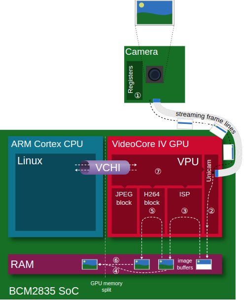
CSI drivers are similarly to camera drivers not always open source or openly documented, and sometimes downstream maintained. But let’s try to focus a bit on Raspberry Pi here. Each of the different RPI versions come with a different Broadcom SOC (but it all started with the Broadcom BCM2835). From a camera perspective nothing too fancy has changed since the first version, apart from the Raspberry Pi 5 which added some extra dedicated camera pre-processor. The CSI receiver has throughout the years always been referred to as the “unicam” CSI receiver, and is actually part of the VideoCore 4 GPU. The drivers are found in the downstream Raspberry Pi fork of the linux kernel, but no open documentation is available outside of that driver. Very recently there has been put some effort into upstreaming the driver to make it more video 4 linux compliant. For the current driver that’s still shipped with the RPI images look at the RPI linux kernel sources. Reading those driver sources learns you a thing or two about how everything has been put together. Actually the CSI block can either be accessed via 2 ways. One way is via the bcm2835-camera driver (that resides in linux staging). Here the VideoCore 4 GPU firmware handles roughly the entire camera pipeline: camera sensor, unicam, ISP, and delivers fully processed frames. Aside of being entirely closed source, there is another important downside to the solution: it only supports 2 or 3 image sensors that Broadcam was asked to support. The second option is via the unicam linux driver, see:
- bcm2835-unicam.txt : device tree documentation for unicam
- bcm2835-unicam.c : driver for the unicam CSI receiver
This driver is able to connect to any sensor with a suitable output interface and V4L2 subdevice driver. This driver handles the data it receives over CSI and copies it into SDRAM. The data is typically in raw Bayer format and the driver doesn’t perform nearly any processing on the data stream aside of repacking. One other aspect of the driver is image format selection. Aside of Bayer other formats are also supported by the unicam driver, e.g. several RGB, YUV and greyscale formats are also mentioned. And of course probing the unicam device is also part of the driver/device bring-up. The main goal of this new driver is leveraging more on the V4L framework, and through that become a lot more flexibility compared to the Broadcom proprietary solution. This option is the off course the most preferred. Understand that both driver solutions are mutual exclusive, thus only one of the two is active at the same time. To select the RPI Foundation kernel driver solution just make sure to make the correct device tree configuration. The RPI driver will be picked up as long as the correct device tree bindings have been defined.
If you want to dive into the new bcm2835-unicam driver you’ll off course recognize many of the same concepts as for the camera drivers, but also some new stuff:
- device tree mapping
- probing
- video4linux device creation
- connecting to v4l subdevices
- start/stop streaming
- part of those functions actually ask the sensor subdevice to start streaming:
ret = v4l2_subdev_call(dev->sensor, video, s_stream, 1);
- part of those functions actually ask the sensor subdevice to start streaming:
- create storage buffers in RAM for the incoming sensor data
- ex: spot the usage of VIDIOC_CREATE_BUFS ioctl (vidioc_create_bufs)
- arrays of supported video formats
Bayer data
Before we go further on the image pipeline let’s first get a quick understanding on what Bayer data is. When reading some of my previous articles about astro-photography we kind of explained how image sensors are build up. They’re like little buckets in which light is collected into tiny photo diodes, and than there is some extra circuitry that converts this electricity into digital values that are transmitted over CSI. The ‘pixels’ can either by mono colored, or RGB through small light filters applied to each pixel individually. It’s not the RGB data that we know in userspace, since each pixel senses only one aspect of the incoming light.
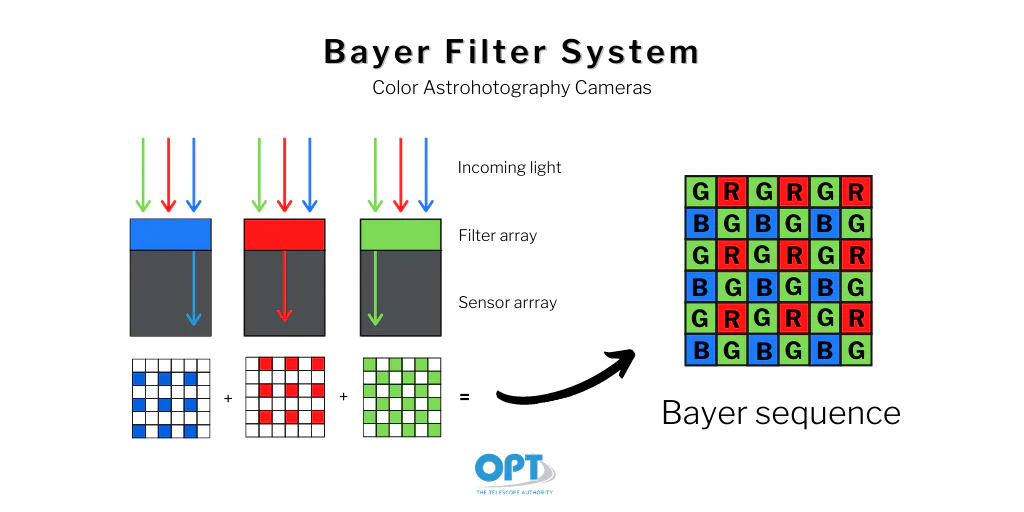
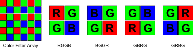
The Bayer filter isn’t always layed out int the same way, it changes over brands and models of sensors, but nearly always packs 2 our of 4 pixels in green as that is what humans are most sensible to.
Per pixel there is an analog-digital conversion that tell us how much light entered the pixel. It’s not a simple per pixel on-off but instead gives us a value in the range of 8 to 16 bits per pixel. The range differs per each sensor. So if we would take a picture and represent the raw Bayer data, and then zoom in so that we can see the individual pixels, than it would look roughly like something in the below.
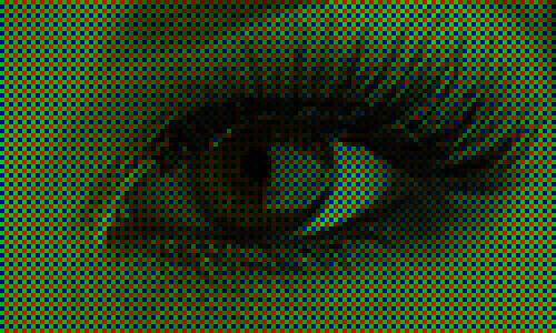
For us the Bayer data by itself is clearly far from what we see in the real world. The image contains noise and the brightness is linear, and it appears for more greener that what you would see in the real world. Further processing needs to be performed. Astro and professional photography fanatics may want to grab the pure raw data directly and perform the image processing themselves in professional software like Photoshop, Siril, etc… Others want to get the picture perfect immediately without post-processing, for example for CCTV purposes, or perhaps in a digital camera such as your smart phone.
ISP: Image Signal Processor
So when the final image result needs to be anything close to how we preserve reality we still have a long way ahead of us. The ISP, short for Image Signal Processor, is a dedicated block of hardware that’s able to perform complex image correction algorithms on the raw image data. The ISP can be an external chip or an internal block as with the Broadcom GPU that’s used on the Raspberry Pi. The ISP can be simple and cheap, but they can also cost several tens of euros per chip and perform intens algorithms like dewarping. Sometimes the signal processing can even be performed in an FPGA or even on the main CPU though means of a SoftISP. According to Bootlin the most important aspects of the ISP are:
- De-mosaicing: interpreting the RAW Bayer data
- Dead pixel correction: discard invalid values
- Black level correction: remove dark level current
- White balance: adjust R-G-B balance with coefficients/offsets
- Noise filtering: remove electronic noise
- Color matrix: adjust colors for fidelity
- Gamma: adjust brightness curve for non-linearity
- Saturation: adjust colorfulness
- Brightness: adjust global luminosity
- Contrast: adjust bright/dark difference
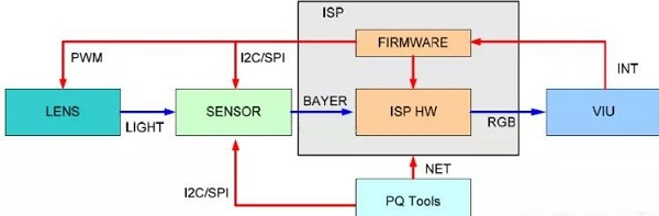
A common task for ISP is running the so called triple-A algorithms:
- Automatic exposition: manage exposure time and gain (optionally diaphragm)
- Auto-focus: detect blurry and sharp areas, adjust with focus coil
- Auto white balance: detect dominant lighting and adjust
A picture will perhaps explain it a lot better here:

To be clear, not all stages have to be performed, it really depends on the application that you’re targeting. But the less processing you perform, the more closer you get to the RAW sensor data which in most cases will be pretty disappointing. An important part of the end result is proper calibration and pipeline tuning. Mostly the hardware ISPs are closed sourced: a black box that takes some tuning params. There is however also the software ISP (ex: libcamera-softisp) that allows you to run these algorithms on a broader range of platforms. Here the RAW Bayer data is collected directly from the V4L framework into userspace where it can be further processed. The soft ISP is very flexible in design, but know that for low latency or high speed processing the hardware ISP is mostly the preferred choice. There are even attempts to run these algorithms on the GPU instead of VPU or CPU as GPUs come with general purpose computing stacks nowadays for fast parallel (per pixel) processing, allowing the flexibility of a software ISP at nearly the speed of a hardware ISP. But nothing comes for free though, understand that GPUs in general consume more power than dedicated hardware ISPs do.
Entire books can be written about all the algorithms that are out there, and the many different implementations that they have. If you want to start diving into this matter and learn something about camera tuning I can encourage you going through the awsome Raspberry Pi Camera Guide.
Oh, and did you know, for a Raspberry Pi:
In fact, none of the camera processing occurs on the CPU (running Linux) at all. Instead, it is done on the Pi’s GPU (VideoCore IV) which is running its own real-time OS (VCOS). VCOS is actually an abstraction layer on top of an RTOS running on the GPU (ThreadX at the time of writing). However, given that RTOS has changed in the past (hence the abstraction layer), and that the user doesn’t directly interact with it anyway, it is perhaps simpler to think of the GPU as running something called VCOS (without thinking too much about what that actually is).
So technically there is a lot that comes into play. Please read the Picamera docs to learn something more about how it grabs image data through the legacy stack.
From kernel to Userspace
User space applications interact with the /dev/videoX device files using standard file operations (open, read, write, ioctl, etc.). These are interfaces created by Video4Linux. When an application performs operations on the /dev/videoX device file, these operations are handled by the V4L2 framework in the kernel. An import thing about the kernel driver is the V4L Device Node Creation: after a driver has successfully registered, the V4L2 framework handles the creation of the device node (/dev/videoX) in the filesystem. The registration typically looks like this:
    ret = video_register_device(&vdev, VFL_TYPE_GRABBER, -1);
    if (ret < 0) {
        v4l2_device_unregister(&v4l2_dev);
        return ret;
    }
The video_register_device() function is key for creating the device node. The V4L2 framework automatically handles the creation and linking of the device file under /dev based on this registration. The device file naming (/dev/video0, /dev/video1, etc.) is managed by V4L2 and the order depends on the sequence and number of video devices registered. Typically /dev/video0 is the one closest to the camera sensor and is also the one that would give you most likely RAW sensor data.
User space applications interact with this device file using system calls (open, ioctl, mmap, etc.). The driver will contain handles for each of these calls. If we again look at the bcm2835-unicam driver we recognize exactly the structure of doing such things:
/* unicam capture driver file operations */
static const struct v4l2_file_operations unicam_fops = {
	.owner		= THIS_MODULE,
	.open		= unicam_v4l2_open,
	.release	= unicam_v4l2_release,
	.read		= vb2_fop_read,
	.poll		= vb2_fop_poll,
	.unlocked_ioctl	= video_ioctl2,
	.mmap		= vb2_fop_mmap,
};
Looking at the open functionality, we see that there is code in place to power-on the sensor:
        ret = v4l2_fh_open(file);
	if (ret) {
		unicam_err(dev, "v4l2_fh_open failed\n");
		goto unlock;
	}

	node->open++;

	if (!v4l2_fh_is_singular_file(file))
		goto unlock;

	ret = v4l2_subdev_call(dev->sensor, core, s_power, 1);
	if (ret < 0 && ret != -ENOIOCTLCMD) {
		v4l2_fh_release(file);
		node->open--;
		goto unlock;
	}
The read functions however is not part of the unicam driver but instead standardised in V4L. In the framework data is made available by memory mapping which avoids copying the data various times throughout the pipeline. Especially also look at mmap = vb2_fop_mmap. The vb2_fop_mmap function is specifically designed to handle the mmap file operation for video devices using the vb2 library. It maps the video buffers, which have been allocated in the kernel space, into the user space so that applications can directly access them. This is crucial for performance in video capture and output applications because it allows user space processes to access hardware-acquired video frames without copying data between kernel and user space, thus minimizing latency and CPU load.
USB Video
Small intermezzo: if you’re using a USB camera instead of the CSI Camera Module, the device is likely handled by a generic UVC (USB Video Class) driver called uvcvideo. This is the standard Linux V4L2 driver for USB video class devices. It automatically creates a /dev/videoN device when a UVC-compatible USB camera is plugged in. The interesting thing here is that you avoid any needs of writing special drivers. However, mostly you’ll be running some USB capable FPGA on the other side of the USB cable that is either pre-tuned well but often also comes with some userspace tools to adjust the calibration. And you have to implement the UVC protocol and so forth, so it’s not entirely without trade-offs. For embedded devices the the preferred choice is mostly MIPI-CSI, if you want to have a plug-and-play solution than USB could be a solution.
Userspace
The final step is to look at how user space applications exactly need to handle the V4L subsystem. The best thing we can do here is write our own application and see if it works.
/**
 * @file capture.c
 * @author Geoffrey Van Landeghem
 * @brief
 * @version 0.1
 * @date 2024-05-09
 *
 * @copyright Copyright (c) 2024
 *
 * Simple application that captures a bunch of camera frames
 * using memory mapping, and saves the 5th frame to disc.
 * The output file is called frame.jpg.
 * The camera input device is /dev/video0.
 *
 * Compile:
 * $ gcc -o capture capture.c
 *
 * Run:
 * ./capture
 *
 * Based upon https://www.kernel.org/doc/html/v4.14/media/uapi/v4l/capture.c.html
 */


#include <stdio.h>
#include <stdlib.h>
#include <string.h>
#include <fcntl.h>
#include <errno.h>
#include <sys/ioctl.h>
#include <linux/videodev2.h>
#include <unistd.h>
#include <sys/mman.h>

#define VIDEO_DEV "/dev/video0"
#define OUTPUT_IMG "frame.jpg"
#define STORE_AFTER_X_FRAMES 5

static int _fd = 0;
static void* _buffer = NULL;
static unsigned int _len_buff = 0;
static int frames_received = 0;

static int open_device(void)
{
    fprintf(stdout, "Opening video device '" VIDEO_DEV "'\n");
    _fd = open(VIDEO_DEV, O_RDWR | O_NONBLOCK, 0);
    if (_fd < 0) {
        perror("Failed to open device");
        return errno;
    }
    return 0;
}

static int init_device(void)
{
    fprintf(stdout, "Querying capabilities device\n");
    struct v4l2_capability cap;
    if (ioctl(_fd, VIDIOC_QUERYCAP, &cap) < 0) {
        perror("Failed to get device capabilities");
        return errno;
    }
    fprintf(stderr, "- DRIVER: %s\n", cap.driver);
    fprintf(stderr, "- BUS INFO: %s\n", cap.bus_info);
    fprintf(stderr, "- CARD: %s\n", cap.card);
    fprintf(stderr, "- VERSION: %d\n", cap.version);
    if (!(cap.capabilities & V4L2_CAP_VIDEO_CAPTURE)) {
        fprintf(stderr, "The device does not support video capture.\n");
        return -1;
    }
    if (!(cap.capabilities & V4L2_CAP_STREAMING)) {
        fprintf(stderr, "The device does not support video streaming.\n");
        return -1;
    }

    fprintf(stdout, "Setting image format\n");
    struct v4l2_format format;
    format.type = V4L2_BUF_TYPE_VIDEO_CAPTURE;
    format.fmt.pix.width = 640;
    format.fmt.pix.height = 480;
    format.fmt.pix.pixelformat = V4L2_PIX_FMT_MJPEG;
    format.fmt.pix.field = V4L2_FIELD_INTERLACED;
    if (ioctl(_fd, VIDIOC_S_FMT, &format) < 0) {
        perror("Failed to set format");
        return errno;
    }
    return 0;
}

static int init_mmap(void)
{
    fprintf(stdout, "Requesting buffers\n");
    struct v4l2_requestbuffers req = {0};
    req.count = 1;
    req.type = V4L2_BUF_TYPE_VIDEO_CAPTURE;
    req.memory = V4L2_MEMORY_MMAP;
    if (ioctl(_fd, VIDIOC_REQBUFS, &req) < 0) {
        perror("Failed to request buffers");
        return errno;
    }

    fprintf(stdout, "Memory mapping\n");
    struct v4l2_buffer buf = {0};
    buf.type = V4L2_BUF_TYPE_VIDEO_CAPTURE;
    buf.memory = V4L2_MEMORY_MMAP;
    buf.index = 0;
    if (ioctl(_fd, VIDIOC_QUERYBUF, &buf) < 0) {
        perror("Failed to query buffer");
        return errno;
    }
    fprintf(stdout, "Buffer length: %u\n", buf.length);
    _len_buff = buf.length;
    _buffer = mmap(NULL, buf.length, PROT_READ | PROT_WRITE, MAP_SHARED, _fd, buf.m.offset);
    if (_buffer == MAP_FAILED) {
        perror("Failed to mmap");
        return errno;
    }
    return 0;
}

static int start_capturing(void)
{
    fprintf(stdout, "Capturing frame (queue buffer)\n");
    struct v4l2_buffer buf;
    buf.type = V4L2_BUF_TYPE_VIDEO_CAPTURE;
    buf.memory = V4L2_MEMORY_MMAP;
    buf.index = 0;
    if (ioctl(_fd, VIDIOC_QBUF, &buf) < 0) {
        perror("Failed to queue buffer");
        return errno;
    }
    fprintf(stdout, "Capturing frame (start stream)\n");
    enum v4l2_buf_type type = V4L2_BUF_TYPE_VIDEO_CAPTURE;
    if (ioctl(_fd, VIDIOC_STREAMON, &type) < 0) {
        perror("Failed to start capture");
        return errno;
    }
    return 0;
}

static int process_image(const void *data, int size)
{
    fprintf(stdout, "Saving frame to " OUTPUT_IMG "\n");
    FILE* file = fopen("frame.jpg", "wb");
    if (file == NULL) {
        perror("Failed to save frame");
        return -1;
    }
    size_t objects_written = fwrite(data, size, 1, file);
    fclose(file);
    fprintf(stdout, "Stored %lu object(s)\n", objects_written);
    return 0;
}

static int read_frame(void)
{
    struct v4l2_buffer buf;
    unsigned int i;
    buf.type = V4L2_BUF_TYPE_VIDEO_CAPTURE;
    buf.memory = V4L2_MEMORY_MMAP;
    fprintf(stdout, "Capturing frame (dequeue buffer)\n");
    if (ioctl(_fd, VIDIOC_DQBUF, &buf) < 0) {
        if (errno == EAGAIN) return 0;
        perror("Failed to dequeue buffer");
        return errno;
    }

    frames_received++;
    fprintf(stdout, "Frame[%d] Buffer index: %d, bytes used: %d\n", frames_received, buf.index, buf.bytesused);

    if (frames_received == STORE_AFTER_X_FRAMES) {
        process_image(_buffer, buf.bytesused);
        return 1;
    }

    if (ioctl(_fd, VIDIOC_QBUF, &buf) < 0) {
        perror("Failed to queue buffer");
        return errno;
    }
    return 0;
}

static int main_loop(void)
{
    unsigned int count = 70;
    while (count-- > 0) {
        for (;;) {
            fd_set fds;
            struct timeval tv;
            int r;

            FD_ZERO(&fds);
            FD_SET(_fd, &fds);

            /* Timeout. */
            tv.tv_sec = 2;
            tv.tv_usec = 0;

            r = select(_fd + 1, &fds, NULL, NULL, &tv);

            if (-1 == r) {
                if (EINTR == errno)
                    continue;
                perror("Failed to select");
                return errno;
            }

            if (0 == r) {
                perror("Select timed out");
                return errno;
            }

            if (read_frame())
                break;
            /* EAGAIN - continue select loop. */
        }
        return 0;
    }
}

static int stop_capturing(void)
{
    fprintf(stdout, "Stop capturing\n");
    enum v4l2_buf_type type;
    if (ioctl(_fd, VIDIOC_STREAMOFF, &type) < 0) {
        perror("Failed to stop capture");
        return -1;
    }
    return 0;
}

static int uninit_mmap(void)
{
    fprintf(stdout, "Memory unmapping\n");
    if (-1 == munmap(_buffer, _len_buff)) {
        perror("Failed to unmap");
        return -1;
    }
    _buffer = NULL;
    return 0;
}

static int close_device(void)
{
    fprintf(stdout, "Closing video device\n");
    if (-1 == close(_fd)) {
        perror("Failed to close device");
        return -1;
    }
    return 0;
}

int main(int argc, char* argv[])
{
    if (open_device() != 0) return -1;

    if (init_device() != 0) {
        close_device();
        return -1;
    }

    if (init_mmap() != 0) {
        close_device();
        return -1;
    }

    if (start_capturing()) {
        uninit_mmap();
        close_device();
        return -1;
    }

    if (main_loop()) {
        uninit_mmap();
        close_device();
        return -1;
    }

    if (stop_capturing()) {
        uninit_mmap();
        close_device();
        return -1;
    }

    if (uninit_mmap()) {
        close_device();
        return -1;
    }
    if (close_device()) return -1;

    return 0;
}
The easiest thing to do here is looking at the function calls in the main body. It gives you a rough idea about what needs to happen at the high level without going into details:
- open the V4L device, typically something /dev/videoN
- check the capabilities of the device, and setup the camera (format, …)
- setup memory buffers. There are a few IO options to handle V4L devices, of which we use the MMAP option. It means we’re memory mapping the V4L device, hence the reference to mmap as that is the system call used. By memory mapping the kernel buffers into our application we avoid the need to copy buffers.Using the VIDIOC_REQBUFS ioctl we can select the buffering mechanism. The location of the buffers can be obtained through the VIDIOC_QUERYBUF ioctl.
- start capturing, typically via VIDIOC_STREAMON
- the main application loop: handle the incoming data. Since we opened the device non-blocking we can use the select syscall to check the file description of the V4L device for updates. When a valid update is ready we should check the memory buffer and do something with the incoming data. In our case we save the content as a JPEG file directly. We can do this without the need of our own jpeg library because we requested the data from kernel space in the V4L2_PIX_FMT_MJPEG format. Our application limits itself to take in 5 camera frames, and save the 5th to disk. Afterwards the application is stopped. It’s often good practice to discard the first frame you get from the camera as it may contain garbage data.
- During application shutdown be nice and make sure to unmap the buffers again and properly close the device
Definitely also look at the code I’ve put in the static functions. For the main loop’s read_frame function you’ll notice how we’re constantly checking for dequeued buffers using VIDIOC_DQBUF. The driver will fill the outgoing buffer with capturing data. If no data is available yet the driver will return EAGAIN. By default the driver has no buffer available to capture into and therefore will not do be able to capture. The application must always assure it first enqueues a buffer before capturing can take place. Not only at the beginnen of the capturing loop, but also after we’ve successfully handled a dequeued buffer we must enqueue a fresh new buffer for the driver to capture into. Enqueuing can be done through the VIDIOC_QBUF ioctl.
Here is the example output seen on the command line:
$ ./capture
Opening video device '/dev/video0'
Querying capabilities device
- DRIVER: uvcvideo
- BUS INFO: usb-0000:00:14.0-6
- CARD: Integrated_Webcam_HD: Integrate
- VERSION: 331285
Setting image format
Requesting buffers
Memory mapping
Buffer length: 614400
Capturing frame (queue buffer)
Capturing frame (start stream)
Capturing frame (dequeue buffer)
Frame[1] Buffer index: 0, bytes used: 6896
Capturing frame (dequeue buffer)
Frame[2] Buffer index: 0, bytes used: 72545
Capturing frame (dequeue buffer)
Frame[3] Buffer index: 0, bytes used: 72540
Capturing frame (dequeue buffer)
Frame[4] Buffer index: 0, bytes used: 73533
Capturing frame (dequeue buffer)
Frame[5] Buffer index: 0, bytes used: 73155
Saving frame to frame.jpg
Stored 1 object(s)
Stop capturing
Memory unmapping
Closing video device
Documentation
There is lots of information to dive into. You can start with looking at the Video4Linux kernel documentation, but you can also study some of kernel drivers that are bound to V4L as I did in this article. Furthermore there are many open-source applications that build on top of V4L, so you may start to explore those as well. And last but not least: search on your favorite search engine if you feel like getting lost.
Conclusive thoughts
Through this article I hope to shed some light upon the inner workings of capturing image data on a linux system. If you look well enough a lot can be learned by reading the official kernel docs, but also by reading code and examining sample applications. The kernel has a wide support for all kinds of video devices, capturing modes, pixel formats, etc. And then there also the many ways of how sensor data can make it to userspace: abstracted via USB, through MIPI-CSI and a soft-isp, through external ISP’s, maybe an FPGA is involved, maybe a binary blob is hiding some part of the image pipeline, maybe the driver is private or maybe only available on a specific kernel fork or upstream branch, you name… All of that makes the V4L framework quite complex to work with and it may scare you a bit as you may not have a clue f where to start. Userspace libraries such as libcamera are made to ease the use of V4L for camera capturing and may be a better starting point if C++ is your thing. Pylibcamera may also work for you if python is more your kind of thing.
