Data conversion

Minor update on the ELM327 OBD scan tool:

A GUI has been added that is auto used when a graphical environment is available, otherwise the program will fall back to console usage. GUI does not contain any usefull controls yet. Users can also force console interface by adding the application launch parameter “-c”. I’ve scanned some of the more convenient PID codes on the Vectra and here and there I’ve also implemented data conversion to make it easy readable. Here is some console output:

PIDS_01_20_SUPPORTED: 01,04,05,0B,0C,0D,0F,10,1C,20,
ERROR: subfunction not supported
ENGINE_LOAD: 0%
ENGINE_COOLANT_TEMP: 25°C
ERROR: subfunction not supported
INTAKE_MANIFOLD_ABSOLUTE_PRESSURE: 100kPa
ENGINE_RPM: 0rpm
VEHICLE_SPEED: 0km/h
ERROR: subfunction not supported
INTAKE_AIR_SENSOR: 30°C
MAF_SENSOR: 0g/s
ERROR: subfunction not supported
PIDS_21_40_SUPPORTED: 21,23,40,
DISTANCE_SINCE_ERROR_INDICATED: 2660km
FUEL_RAIL_PRESSURE_CT_VACUUM: 0kPa
ERROR: subfunction not supported
PIDS_41_60_SUPPORTED: 60,
ERROR: subfunction not supported
PIDS_61_80_SUPPORTED:
ERROR: subfunction not supported

The program also comes with auto auto incremented version numbers, this is made through Ant Build tasks. The program version can be checked in a About form.
Furthermore I found more interesting reads:

http://www.canbushack.com/blog/index.php?title=scanning-for-diagnostic-data&more=1&c=1&tb=1&pb=1

https://pcmhacking.net/forums/viewtopic.php?f=3&t=3224&start=350

Back on the Vec(tra)

Some time ago I made a first OBD interface circuit for a Opel Vectra, and I even got some data back that I could at least interpret and check against the data displayed on the car’s dashboard. Now I quickly found out that there is more than meets the eye. There are a lot of different standards and I was not quite sure which one exactly is used in the Opel Vectra C. However, I did found out about the ELM327 and STN1110 IC who allow interchanging data over OBD in a more controlled way. Under the hood of both these devices is a PIC microcontroller so in fact there is not really anything special about the circuitry, there is just the firmware doing its magic abstracting things away for who over uses these IC’s. You can order the IC or you can pick up end-products for as low as € 20, and because it hides some of the more complex OBD protocol features it is really a good toy to get you going on OBD reading. There is also a datasheet that explains how developers should interact with the ELM327, really handy! I picked up one of these (which is obviously a Chinese clone of the real ELM327 interface):

The ELM327 based devices can be had in different types: USB, WiFi, BT, RS232… And once we have this off course we go back to our previous code and adopt it to our new interface, and after some experimenting I have a basic command line mode way of exchanging data running. Until now the tool allows for auto detecting the interface, connect to it and then ask the user which commands he would like to execute. The console then replies which whatever data is received.

Currently I’m also working on logging what ECU’s we have been talking with, creating a more user friendly form based user interface, make the software auto config the ELM327 for correct operation, save some user data on disk. Other stuff I would like to add is a monitor mode, some debug logging, set up the software to allow translations of texts.

Here is some of the console output I was able to create today:

run:
Not connected
Scanning for serial ports
Stable Library
=========================================
Native lib Version = RXTX-2.1-7
Java lib Version = RXTX-2.1-7
Scanning serial ports completed
=========================================
Auto detecting ELM327 device
Connecting to serial port
Connected to /dev/ttyUSB0 @ 38400 baud/s
=========================================
READY
Enter command: ATH1
ATH1
OK

Enter command: AT@2
AT@2
?

Enter command: AT@1
AT@1
OBDII to RS232 Interpreter

Enter command: ATH1
ATH1
OK

Enter command: 0101
0101
7E8 06 41 01 81 06 80 00

Enter command: 0105
0105
7E8 03 41 05 3C

Enter command: 0104
0104
7E8 03 41 04 00

Enter command: ATD
ATD
OK

Enter command: ATDP
ATDP
AUTO, ISO 15765-4 (CAN 11/500)

Enter command: 0151
0151
7F 01 12

Enter command: 0902
0902
7F 09 78
014
0: 49 02 01 57 30 4C
1: 30 5A 43 46 33 35 34
2: 31 90 90 90 90 90 31

Enter command: STOP
Not connected
Experimental: JNI_OnLoad called.
BUILD SUCCESSFUL (total time: 5 minutes 40 seconds)

The ELM327 allows AT commands to configure it, if a commands is received that does not begin with “AT” than the command is considered to be an OBD command in which the replies differ in layout as you may have noticed in the output above. Command ATH1 sets the ELM to display OBD packet headers from which we can retrieve address info. A bit later, the OBD command 0105 replies with “7E8 03 41 05 3C“. Because we’re talking about CAN replies here (11bit CAN, 500kbaud), 7E8 is the address of the replying ECU. 03 tell us that we’re receiving 3 byte’s of data. The first byte of data, 41, tell us it is a response to a mode 01 request (01 + 40, 40 is a constant number to differentiate replies from requests). The next byte 05 is a copy of the 05 OBD PID that is also found in our request. The final byte is where the actual data sits. 3C is a hex number (as all the others are), if we convert it to a decimal number we get 60. The formula for OBD mode 01 PID 05 states that we should take 40 from this decimal number in order to get the correct result, and so 60 – 40 equals 20, a possible temperature for a cold engine. In the next post I’ll hopefully be able to show a little more user interface and less OBD details, a presto!

Opel/Vauxhall Vectra CAN interfacing

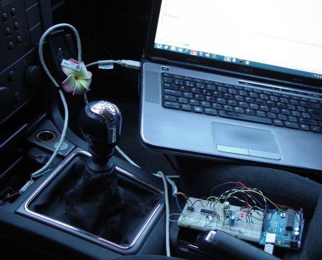
Since I got this car second hand it has been through a series of faults, failures and repairs (which is actually hard to avoid at a mileage of 150k+ km), but the cost of taking it to the Opel dealer every time pushed me in to the direction of doing some of the car repairs myself lately. The down side, the car being made in 2004, is full of sensors and so whenever a problem arises it is quite hard to make good  diagnosis without proper tools to read out this sensor data. Many times, engine failures are due to malfunctioning sensors for example. And so I started to think about interfacing the cars CAN bus and see what data I can get, unfortunately this is not like opening a serial terminal and watch data appear…

First of all there is this CAN bus which is a two wire (CAN-H, CAN-L) physical layer and on top of that a kind of networking layer which makes CAN look more like a networking protocol than the common RS232 serial link. As I’m not the only one to think of such a project I found quite some info online and also some libraries for Arduino to get me started. I also looked at some of the info I could get out of the Chinese Op-com clone I have around here, but unfortunately the unit had died.

Some Arduino CAN bus projects:

Canduino: https://code.google.com/p/canduino/

Seeed studio CAN-BUS shield: http://www.seeedstudio.com/wiki/CAN-BUS_Shield

Sparkfun CAN-BUS shield: https://www.sparkfun.com/products/10039

SK Pang CAN-BUS shield: http://www.skpang.co.uk/catalog/arduino-canbus-shield-with-usd-card-holder-p-706.html

Furthermore there is also some info regarding making a Raspberry-pi based CAN interface:

http://elinux.org/RPi_CANBus

http://lnxpps.de/rpie/

Another good link is this one with some basic CAN bus functionality explained and a Arduino schematic:

http://modelrail.otenko.com/arduino/arduino-controller-area-network-can

And the “Hacking You Car” article by Marco Guardigli:

http://marco.guardigli.it/2010/10/hacking-your-car.html

All together, most projects use a MCP2551 CAN transceiver and MCP2515 CAN controller so most schematics looks more or less the same and so one can use one schematic and try the different software libraries that are available for Arduino. And so I took the ODB connecter from the broken Op-com unit and used it in my own schematic which looks more or less like this:

schematic

DSC05983 DSC05981

After trying some of these libraries I noticed that the SK Pang library is the easiest one to quickly get some data out of your car. Although the default Arduino code allows to get out some basic engine info easily and in a human readable way, I found not very impressive and so I’m now exploring on how I can modify the code the get more info out of the car. In the latest SAE J1979 OBD standard there are 10 modes of functioning described, where SK Pang uses mode 1 ($01. Show current data) to request and show the engine data.  Requests depend on the PID (packet indentifier) one sends, whenever a ECU responsible for this PID sees the request it will get the data and respond. Standard PIDs can be found online here: http://en.wikipedia.org/wiki/OBD-II_PIDs. And  so I started trying every combination in between 0 and 255 to see which ones I can get a reply to, here is some of the info:

#Reply: 0*152#
#Reply: 1*129#
#Reply: 5*65#
#Reply: 11*103#
#Reply: 12*24#
#Reply: 15*62#
#Reply: 16*11#
#Reply: 32*160#
#Reply: 35*20#

the first number is the PID, the second one is its value, both in decimal form. To get human readable output one has to look up the code and use the appropriate method to convert the data into a correct format. For example, the frame with PID 5 (0x05 in HEX value) contains the engine coolant temperature, the formula is as following: A-40. And so, our engine coolant temperature is 65-40=15°C.